Let's summarize what you’ve learned up to this point. A database is like a warehouse. Its purpose is to feed information to a computer program like a warehouse containing raw materials feeds a clothing manufacturing factory. Between the warehouse and the factory, a DBMS manages the warehouse.
As you’ve seen, data can sometimes be very structured — or not. This course shows how to model a database for structured data (data about filming locations), which means we will use a relational database.
But what does modeling mean?
Well, modeling means organizing the structure of the database so that it can store your data most effectively.

Designing the shelving layout is like modeling your warehouse, and this process starts with a pen and paper (well, nowadays, you can draw on your computer, of course! ).
There would be several steps to modeling a large warehouse:
This last step is very technical and necessary for the technicians building the shelves.
The same principle applies to modeling a database, and it typically involves three steps:
The first step is the conceptual data model (CDM), which has three sub-steps:
1. Identify the entities present within the data.
For example, filming location data have the following entities:
2. Identify the relationships between these entities.
3. Assign a multiplicity to these relationships, using 0 , 1 , 1..* , 0..*, , etc.
There's no need to understand this for the moment, but bear in mind that a multiplicity allows you to specify, for example:
There are several options when designing the conceptual model. The most common are:
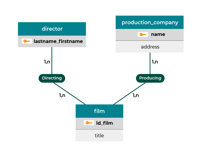
These two modeling methods are similar in principle, although they use quite different diagramming conventions. For example, an ER model looks like this:

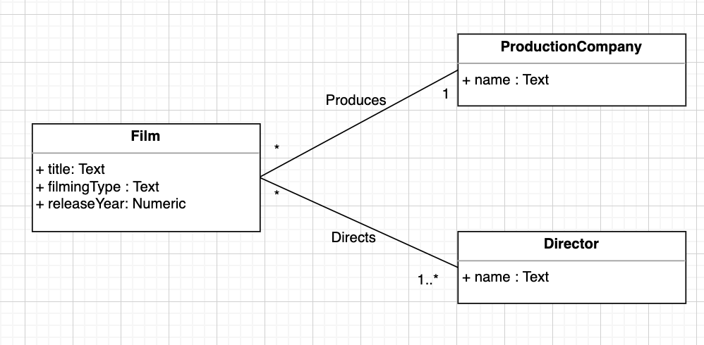
Whereas a UML class diagram looks like this:

Do I need to use both?
No, you can just choose one.
We will use the second option, the UML class diagram, for this course. This approach has several advantages:
The conceptual model is a set of entities. But now, these entities need some structure.
Remember that structured data can be represented in the form of tables. Well, that’s the next step: formatting all of the entities into tables.
You are going to build the logical data model (LDM). This time, you don't have a choice between different modeling techniques like for the CDM. So you’re going to use the relational model.
In relational modeling, you store data in a table.
The main process you use to get from UML to a relational model is transforming multiplicities into foreign keys. Does the idea of a foreign key seem a bit “foreign” to you? Don’t worry — you’ll get it. 🙂
Now you’re getting closer to the technical solution because you’re starting to shape the data so that an RDBMS can use it.
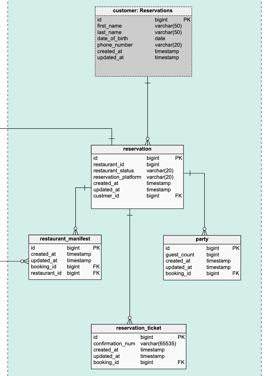
Here’s an example of a relational model:


Note that you no longer display the multiplicity (this information is important for the quiz, but shhh for now!).
Can’t we do the conceptual model? The LDM will be a lot of work!

Don't worry! The LDM flows quite naturally from the CDM. So you don’t need to think too much; you need to apply the basic transformation rules to get from the CDM to the LDM.

You're going to need to talk to the machine that will hold your database. As you know, if you want to talk to a computer, you need to use code. Yay!
So, the final step is to translate the relational model into code your chosen RDBMS can understand (e.g., PostgreSQL, MySQL, Oracle, SQLite, etc.).
Even if the RDBMS understands SQL, there are sometimes differences as each RDBMS has its own variant of the SQL language.
SQL can be broken down into four languages:
When modeling a database, use the DDL (data definition language).
Here’s an example of DDL (creating a table in SQL):
CREATE TABLE film ( film_id INT PRIMARY KEY, title VARCHAR(100), genre VARCHAR(100), release_year DATE )Transforming the LDM into the PDM is an automatic process, and often these two models are confused and sometimes merged into the same diagram.
We're only going to look at the first two levels: the CDM and the LDM. To create the PDM, you need to use SQL, select an RDBMS, and install it. We are not going this far, so we can keep the course short. But you can use SQL in our other course, Implement a Relational Database With SQL.
It’s going to be frustrating to design the CDM and LDM schemas without manipulating the filming location data!
Yes, okay. We will have a chapter that will allow you to structure your data and use it to populate the SQLite RDBMS (as this is the simplest one to use). In addition, we’ll supply you with SQL code that you can copy and paste.

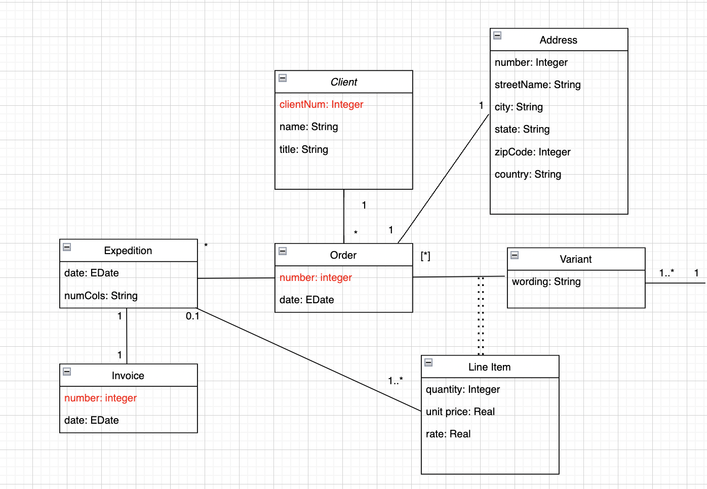
Right, let's do a little exercise. Use the conceptual model for a database in the form of a UML class diagram provided below.

2. Now go a bit further and imagine what features this software might have and how it can be used.
Wait, don't check the answer too soon!
Answer:
It’s a database used by an order and invoice management system (e.g., a shop).
The software stores details of all items for sale, each belonging to a category. It also allows orders to be generated, which can relate to one or more customers and a delivery address.
When the order ships, it is recorded automatically in the software, and there is an invoice attached.
Reference table for structured databases:
Modeling level
Abbreviation
Description
Illustration method
Diagram that can be understood by a human
ER Model (MERISE)
Class diagram (UML)
Translation of the CDM into a relational structure common to all RDBMS
Very specific to the selected RDBMS, often written in SQL
SQL – DDL (data definition language)
Now you know what database modeling means. But you need to understand that all models are not equal. In the next chapter, you’ll discover the necessary fundamental criteria for a high-quality model.